Reconciling HVAC Equipment Across CAD Plans and Schedules
A practical method for reconciling HVAC equipment symbols, tags and schedule rows into traceable instance counts while exposing duplicates and unresolved discrepancies.
A practical workflow for verifying drawing units, insertion transforms and coordinate references before using multidisciplinary overlays for engineering measurements.
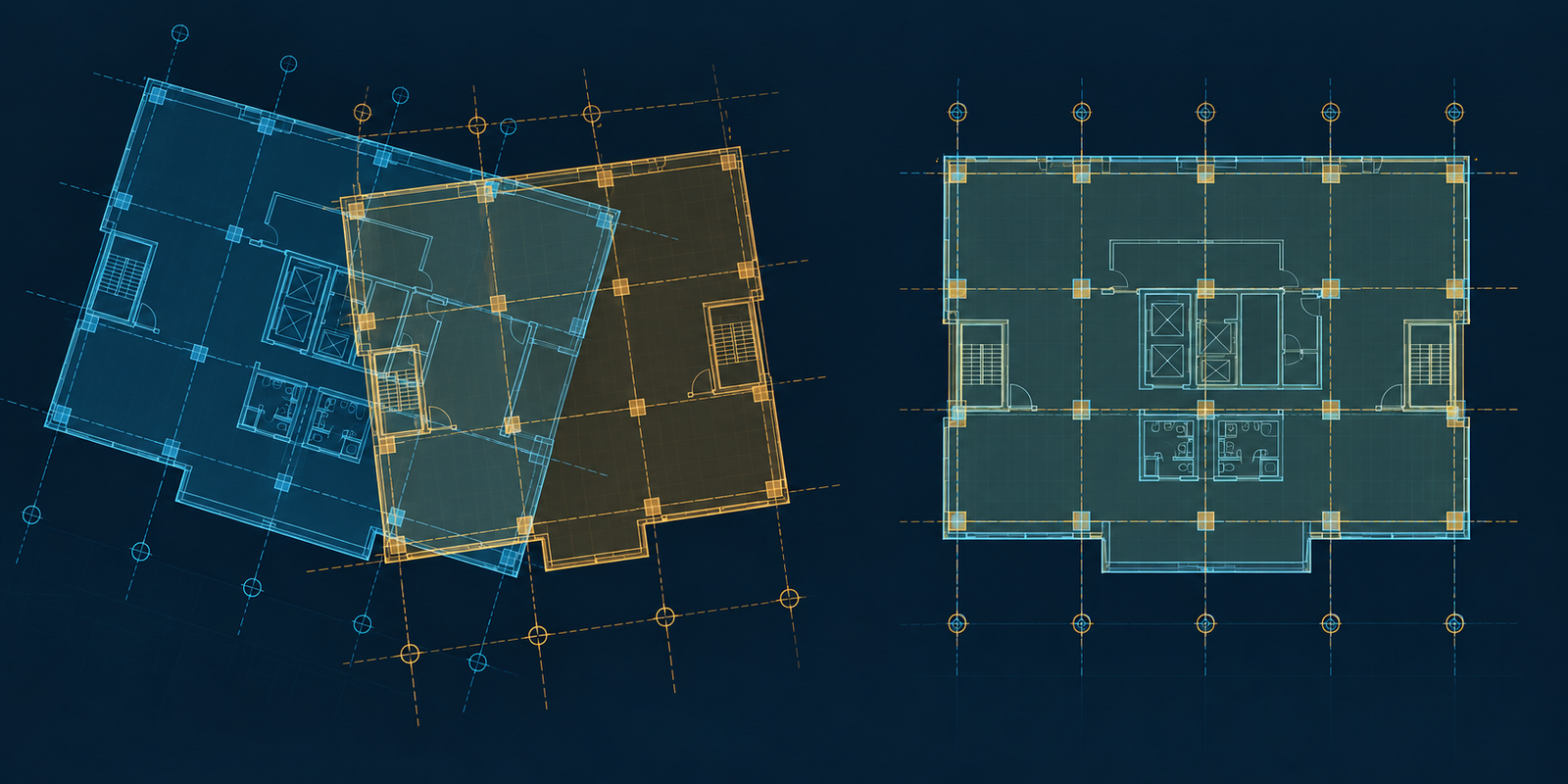
A coordination overlay can look convincing while its measurements are wrong. Two drawings may share a recognizable floor outline but use different units, different origins, or different rotations. A reviewer who starts by moving one plan until it appears to fit can conceal the original error and make the next revision harder to reconcile.
Before comparing pipe routes, structural openings, or plant-room clearances, establish how each source drawing maps into the coordination space. The following is a proposed quality-control workflow for drawing-based coordination. Its numerical examples are illustrative, not project requirements or survey instructions.
Start with the intended use. A visual review of service zones needs a different level of evidence from a dimensional check of a prefabricated assembly. Record the disciplines, floors, revisions, and model-space content involved. Identify the project's agreed coordinate reference and obtain its unit and datum definitions from the responsible team.
Preserve the incoming files. Perform experiments in a controlled coordination copy and keep a record of every applied transformation. A drawing that has been manually shifted without a recorded offset is difficult to audit: a later reviewer cannot distinguish a deliberate coordination adjustment from an authoring error.
Also separate a common coordinate frame from a common engineering meaning. Aligned linework does not prove that the drawings represent the same issue date, construction stage, or elevation. A demolition plan and a proposed-services plan can occupy the same coordinates while describing different physical conditions.
AutoCAD's INSUNITS setting specifies the drawing-unit value used for automatic scaling of inserted or attached content. Autodesk also documents an exception for annotative blocks. Treat this setting as relevant evidence, rather than a guarantee that every existing entity was drawn consistently. [Autodesk: INSUNITS](https://help.autodesk.com/cloudhelp/2025/ENU/AutoCAD-Core/files/GUID-A58A87BB-482B-4042-A00A-EEF55A2B4FD8.htm)
Check a known model-space distance against an independently confirmed project dimension. Prefer a clearly identified grid spacing or another controlled reference over an object whose size is only assumed. Measure the actual endpoints; a visible text label alone does not establish the geometric distance. Repeat the check in another part of the drawing and, where possible, along a different direction.
Consider an illustrative file in which an agreed six-metre grid interval measures 6000 drawing units. Millimetres are a plausible interpretation. If the interval measures 6, metres are plausible. Neither result, by itself, establishes the correctness of the entire drawing. A single block could have a local scale that differs from the surrounding model.
Maintain separate fields for declared units, verified geometric interpretation, and unresolved discrepancies. This avoids turning a convenient assumption into an undocumented fact. If the evidence conflicts, stop the affected dimensional comparison and request a clarified source.
Autodesk describes insertion scaling as a combination of unit-related settings and an additional insertion scale factor. Unitless content can involve source and target override settings, and the insertion method can affect behavior. The practical implication is to inspect the resulting geometry in the coordination file, rather than relying only on a source-file setting. [Autodesk: Block Units and Insertion Scale](https://help.autodesk.com/cloudhelp/2025/ENU/AutoCAD-LT/files/GUID-6C46049D-8636-442D-8BAC-CF4FD515FDC0.htm)
For example, converting coordinates expressed in millimetres to a coordination space expressed in metres requires a factor of 0.001. An 8000-unit interval then becomes 8 metres. If automatic insertion has already made that conversion, applying another factor of 0.001 would produce 0.008 metres. The arithmetic is straightforward; the challenge is identifying which conversion has already occurred.
Record the effective transformation of the attached content, including scale, rotation, and translation. Where references or blocks are nested, assess the complete chain that affects the geometry of interest. Avoid assuming that the top-level insertion describes every nested object.
Nonuniform scaling deserves separate review. If an intended physical layout is stretched differently along two axes, an apparent alignment in one direction can hide a distortion in the other. Do not correct such a discrepancy by stretching a discipline plan to match another without establishing why the sources disagree.
Autodesk defines the UCS as a movable coordinate system and the WCS as the drawing's fixed world coordinate system. The UCS affects coordinate entry and orientation-related operations. A convenient drafting orientation is therefore not sufficient evidence that two files share the same project reference. [Autodesk: User Coordinate System](https://help.autodesk.com/cloudhelp/2025/ENU/AutoCAD-LT/files/GUID-C16311B2-789B-4A9A-8F73-BE27C901ED05.htm)
For coordination, document what origin and axis directions the team intends to use. Describe any mapping from a local building grid to a site reference. Do not equate the CAD term “world” with a verified geodetic coordinate system: project documentation must establish that relationship.
A plan may be presented with the building conveniently horizontal on screen even when the agreed site orientation differs. Review numerical coordinates and reference information, not just the displayed view. The same principle applies to elevation: a local floor datum and a site datum need an explicit relationship before vertical comparisons are meaningful.
A simple two-dimensional mapping can be written as p = sRq + t, where q is a source point, s is a uniform unit or scale factor, R is a rotation, t is a translation, and p is the resulting coordination point. This is an explanatory model for planar alignment, not a substitute for a project's survey transformation.
As an illustrative calculation, let q be (4000, 2000) millimetres, s be 0.001, the rotation be 90 degrees counterclockwise, and t be (100, 200) metres. Unit conversion gives (4, 2) metres. Rotation gives (-2, 4) metres. Translation produces (98, 204) metres. Every term added at the last step is expressed in metres.
One matching point can demonstrate position at that point but cannot establish orientation or scale. Two distinct matching points constrain more of the mapping, yet a third independent, non-collinear checkpoint provides an important opportunity to detect a mistaken correspondence or distortion. Use distributed checkpoints rather than concentrating all evidence in one corner.
Calculate and record the residual difference between transformed and reference coordinates at each checkpoint. The project team should define acceptance criteria appropriate to the intended use and source quality. There is no universal residual threshold that makes every drawing suitable for fabrication, setting out, or clash assessment.
An alignment review should explain the evidence, not simply announce that a file passed. Similar offsets at several checkpoints suggest a translation discrepancy worth investigating. Differences that grow with distance may indicate scale or rotation issues. An isolated mismatch may be a revision change, a drafting inconsistency, or an incorrectly selected checkpoint.
These patterns are diagnostic clues, not automatic diagnoses. A building wing may have changed between revisions; forcing it into alignment could erase real design information. Compare revision records and confirm checkpoint identities before altering the mapping.
Keep geometry checks separate from discipline interpretation. Even a correctly aligned pipe centreline does not establish the outside insulation envelope. A structural opening outline does not automatically prove the available installed clearance. Coordinate validation makes subsequent comparisons possible; it does not supply missing engineering properties.
An automated pipeline should retain the source filename, revision, entity identifier where available, nesting path, native coordinates, declared units, effective transformation, and transformed coordinates. Link each derived measurement back to its supporting geometry and reference evidence.
Retain uncertainty as data. Useful review states include “units verified,” “units inferred,” and “coordinate reference unresolved.” These are proposed workflow labels, not software-standard statuses. A system should avoid silently promoting an inferred mapping to a verified one merely because the visual overlay looks plausible.
For extracted objects, distinguish the position of a symbol insertion point from the position of the physical feature being checked. A symbol's base point may be convenient for drafting rather than representative of a connection or equipment boundary. Identify the actual feature relevant to the engineering question before calculating a distance.
Changes should trigger targeted revalidation. If a revised reference changes its unit declaration, insertion transform, or checkpoint positions, invalidate the affected alignment approval and review downstream results. Preserve prior evidence so the reviewer can explain why a previously accepted measurement changed.
A compact review record should state the source revisions, comparison purpose, adopted units, coordinate reference, effective transformations, checkpoint residuals, unresolved issues, and responsible reviewer. Include enough information for another engineer to reproduce the overlay without guessing.
If an unresolved mapping affects only one discipline or zone, identify that boundary explicitly. Do not describe the complete package as verified when only part of it was checked. Likewise, avoid assigning physical certainty to measurements derived from schematic or deliberately simplified linework.
Reliable coordination starts before the first clash is examined. Establish the units, document the reference frame, validate the mapping at independent locations, and preserve the evidence behind every transformation. That foundation turns a visually persuasive overlay into a reproducible engineering comparison.